Saturday, May 9, 2009

Weeling Display goes to PCB

It's time now to create a real PCB for the Weeling Display, so everyone of you could create his own Weeling Traction Control.

First of all, if you do not know, just have a look to the old posts:
Display It!
Display It! (Cont...)
XE164 to Display connections

After the debug and the "in circuit" test, I drawn the schematic using Eagle (Eagle 5.5.0), here you can see it:

the above is the version with 9 displays in order to monitor:
- Gear (it's the display in the middle and it's a bigger model)
- Engine RPM or Speed
- Oil Temperature or Weeling Percentage (how much the rear weel is spinning in percentage)

Using the freeware Eagle version, is not possible to route a so big display, so I have reduced to 7 Displays and reoute as follows:


here the bottom Layer:


here the top Layer:


Component side is:


Component List:

Exported from WeelingDsiplay.sch at 5/2/2009 5:07:31 PM

EAGLE Version 5.5.0 Copyright (c) 1988-2009 CadSoft

Part Value Device Package Library Sheet

C1 100uF 25V
C2 100uF 10V
DIS1 HD-H103
DIS2 HD-H103
DIS3 HD-H103
DIS4 HD-H103
DIS5 HD-H103
DIS6 HD-H103
DIS7 HD-H103
DIS8 HD-H103
GEAR HD-N103 display-hp
IC1 4511N
IC2 7805
POWER 12V
R-D 330 ohm
R1 330 ohm
R2 330 ohm
R3 330 ohm
R4 330 ohm
R5 330 ohm
R6 330 ohm

R7 330 ohm
R8 330 ohm
R9 330 ohm
R17 330 ohm
R18 330 ohm
R19 330 ohm
R20 330 ohm
R21 330 ohm
R_A 330 ohm
R_B 330 ohm
R_C 330 ohm
R_E 330 ohm
R_F 330 ohm
R_G 330 ohm
T1 BC373-NPN-TO92
T2 BC373-NPN-TO92
T3 BC373-NPN-TO92
T4 BC373-NPN-TO92
T5 BC373-NPN-TO92
T6 BC373-NPN-TO92
T7 BC373-NPN-TO92
T8 BC373-NPN-TO92
T_GEAR BC373-NPN-TO92-CBE TO92-CBE transistor 1
X1 2520- 2520- PAK100/2500-20 con-3m 1


Currently I'm trying to build my first PCB, pictures will come soon...

Friday, May 1, 2009

Some pictures

Here the Weeling Box and display connected to the Yamaha R6:


Friday, April 17, 2009

Traction Control Connections

Weeling in mounted on my Yamaha R6, I still have to decide how to operate the Traction Control and how to connect it to the byke ECU.
Thinking and rethinking I had the idea to connect the traction control as the Electronic Shift units are doing. I found the following instructions:

so, if I have correctly understood the idea is to cut the power supply of the fuel injectors or of the spark coils.

Some friend told me that avoiding the spark firing could be that the spark get wet and therefore damaged... not really nice!!! Most likely is better to interrupt the fuel Injection.

From the R6 manual (2003 model), I have extracted the following electrical circuit:

(where "12" is the POWER SUPPLY RELAY and "18" are the fuel injectors).

The idea could be to use an HV P-MOS transistor and turn off the power supply of the fuel injectors as:


The driver circuit could look like:


Someone have some idea or suggestions?

Friday, April 10, 2009

Yamaha R6 (2003 Model) Water Temperature Sensor

Finally I was able to connect my "Welling" to the Yamaha R6 (2003 model) ECU in order to acquire the water temperature.
I explayin how to do, looking to the Yamaha R6 electrical circuit manual, the water temperasture sensor (#23 in the picture) is directly connected to the ECU:

Therefore is quite simple to connect it: just take a cable and solder it on the ECU connector G/W (Green/White- mainly is a green cable with a little white stripe) cable, bring it to the XE164 KeyChain and compute the temperature as:
uiTmp = (unsigned int) ( ((float) ( uiTemperature >> 4) ) * (-1.32) + 127.42 )
/*
uiTemperature is the 12-bit ADC converted values, before temperature calculation I reduce the precision to have stable temperature visualization (I do not need so high precision)
*/


I've used such equation since I have desumed from the Yamaha manual the following NTC curve (it declares that the NTC has 6.37KOhm at 0°C and 0.35kOhm at 80°C):
Temperature Vs. NTC resistance

The same could be plotted as Temperature Vs. ADC Voltage
Temperature Vs. ADC Voltage

Looking to the same, but plotting Temperature Vs. ADC value in the range 60°C .. 110°C (the most important temperature range), we get:
Temperature Vs. ADC value
and this is what I measured:

After a little rearrangement, I fit it better:

Now I calculate the SLOPE and the INTERCEPT (I assume a linear equation to have a simple calculation):
SLOPE = -1.32
INTERCEPT = 127.42

Thursday, April 2, 2009

Traction Control Settings (Con't)


As promised, here it comes the debug... So, the only bug I discover was that in my calculation I have used 10-bit ADC resolution, but in reality the XE164 has 12-bit resolution (from 0 to 4095), so the only modification I did was to shift the value as:
uiTmp = ( ADC1_RESRA0 >> 2 ); // Get latest Manettino value
Moreover I have added a piece of code to show on display the TC settings, the meaning is: At the end the weeling electronics in its little box is:

Wednesday, April 1, 2009

Traction Control Settings

As you can immagine, I'm continuosly thinking on how to tune the Traction Control (TC). One idea could be to flash some key parameters or to control it more easily. Looking around I've seen this very interesting solution:
(Bazzaz)
I like since seems user frendly... I try to go for it!


Step 1
first is to select the adjustment switch: I go for a 10K potentiometer since it is cheap and I think it ca do all what I need. In order to give fashion to it, I like to call it as "MANETTINO" like Ferrari does for a similar stuff they have on the dashboard (by the way, manettino means "tiny handle").

Step 2
I try to define what I really need: I like to be able to change the TC threshold (I mean when it starts to work) and the sensibility (I mean how much strongly reduces the engine tourque).

Step 3
Potentiometer working definition:
- each 40° of potentiometer revolution I like to change the TC threshold as:

Fig.1) depending on manettino position, the potentiometer output voltage is changed from 0V to 5V corresponding to OFF, 110%, 120%, 130%, 140%, 150% and 160% threshold factors.


- inside each 40° of potentiometer revolution I like to modulate the TC sensitivity giving a progressive change in both sensitivity:

Fig.2) depending on manettino position, the TC threshold is changed from OFF, 110%, 120%, 130%, 140%, 150% and 160%. Once the threshold is selected, the sensibility can be adjusted from 0 to 1


Step 4
The circuit to be added is quite easy: I add just one potentiometer from 5V to GND, the cursor is connected to the ADC_1 channel 0.

Step 5
Off-line calculation: in order to write the software I need to write down all the variables and try to build up a model: I use a spreadsheet - what else!
This is what I generate, I know is not so easy to understand, but it shows how the manettino position is converted to voltage and to ADC value and then to TC threshold and TC sensitivity:


Step 6
Now is time to think about the software changes. First I need a couple of new static variables:
- uiTC_Threshold
- uiTC_Slope
and then I need to configure the ADC_2 for cntinuous conversions, I use DAvE as usual:

I like to limit the "manettino" changes only when the bike is not running, therefore, in the OFF state I add the following lines:
uiTmp = ADC1_RESRA0; // Get latest Manettino value
if ( uiTmp > 150 )
{
uiTC_Threshold = 1000 + ((unsigned int)( uiTmp / 151 ) * 100); // 110% is 0.74V
uiTC_Slope = ( uiTmp % 151 ); // Remainder
} else {
uiTC_Threshold = 0;
uiTC_Slope = 0;
}


Step 7
I need now another timer to modulate the engine tourque as calculated by the TC, I use Timer_7 from the CC2 unit:

The selected resolution is 15.515 usec, therefore to conver the ADC value into timer counter value, I just need to multiply by 432:
// Traction Control Timer Calculation
CC2_vLoadTmr ( CC2_TIMER_7, uiTC_Slope*432 );

The last stuff is to toggle port P10.7: the software turns it on, the Timer 7 Interrupt Service Routine turns it off:


IO_vSetPin( IO_P10_7 ); // TC-OFF to HIGH

...

void CC2_viTmr7(void) interrupt CC2_T7INT
{
// TC-OFF signal to LOW after timer expires
IO_vResetPin( IO_P10_7 ); // TC-OFF to LOW
} // End of function CC2_viTmr7


Step 8
well, last step is to test it! I'll do tomorrow...

Tuesday, March 31, 2009

Accellerometers and traction control


As my friend Fabio suggested, I should include some accellerator sensors to better perform the traction control.

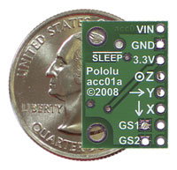
The task should not so difficult since there are many accellerometers on the market even for low prices. In particular, I think is better to look at those having a digital interface (i.e. IIC2 or SPI bus) instead of those having pure analogue output. Looking around I've found many but all have tiny pacheages so are really difficult to be soldered! Thanks to FuturaElettronica we can get a soldered 3-axis accellerometer for only 13€: link.

How it works?

The digital accellerometers are MEMS componenet having one floating part inside that goes to change 3 capacitances (each capacitor is perpendicular to each other: one in X direction, one in Y and one in Z), the capacitance variation are then converted to digital signals by appropriate circuitry integrated on the same die. Typically they could measure +/-1.5g or +/-6g, but for the byke the +/-2g should be enough, so the MMA7455LT could be ok.