Saturday, December 20, 2008

Engine Considerations

I'm sure that reading MaxECU you got the impression that something is not clear or is simply difficult to understand it.
I try now to share my mechanic considerations: let's talk about the engine and the power transmission and tourque. I do not like to repeat what is already available in Wikipedia at: http://en.wikipedia.org/wiki/Horsepower (or in italian language: http://it.wikipedia.org/wiki/Coppia_motrice), in particolar is important to mention the following relationship between Tourque, RPM and Power:


In simple words our byke works like this: the generated power is constant and depends only on the used engine, while the Tourque available at the rear weel is depending on the used gear, on the final transmission ration and on the weel circonference (so depending on how much we have inflate the tyre, the temperaure, ec..).
Yamaha declares for the R6 2003 model:

Gear Ratio - 1st Gear 37/13 (2.846)
Gear Ratio - 2nd Gear 37/19 (1.947)
Gear Ratio - 3rd Gear 28/18 (1.556)
Gear Ratio - 4th Gear 32/24 (1.333)
Gear Ratio - 5th Gear 25/21 (1.190)
Gear Ratio - 6th Gear 26/24 (1.083)

Primary Reduction Ratio 86/44 (1.955)
Secondary Reduction Ratio 48/16 (3.000)


The final transmission ratio is (just multiply the above numbers):
Gear Ratio
1 -> 0.54
2 -> 0.79
3 -> 0.99
4 -> 1.15
5 -> 1.29
6 -> 1.42

Therfore the final model for Engine RPM = 6000 (g/min) is:

Now, assuming the Rear Weel circonference as 2.83m, I calculate:


Here another calculation sheet for Engine RPM = 12000 (g/min):

The above Engine Hz and RearWeel Hz values has been used for the software debug and simulation.

At the end, with such model I was able to simulate the accelleration speed on the Mugello Circuit Streight, here the result:

Thursday, December 18, 2008

DAvE Development Tool


The Max ECU software development is done using the given Infineon DAvE tool.

What is DAvE:
DAvE is a graphical software generator to support CPU configuration and to generate the C files templates. It permits to configure each system's peripherals (timers, Watch-Dog, serial communication, CAN nodes, PWM, etc...), to configure the Ports (input, output) and the system frequency (with or without PLL, depending on our needs). Moreover DAvE generates C code directly compilable with the supported tool-chains (Keil, Tasking, ...). DAvE is free and can be downloaded from Infineon site: http://www.infineon.com/cms/en/product/channel.html?channel=db3a3043134dde6001134ee4d3b30265.
If you buy a development kit (from: http://www.ehitex.de/p_info.php?xPD=113_117&products_id=264), you'll get all what you need, included the limited version of the compiler and debuggers.
DAvE also gives you training material (called HOT, also downloadable from Infineon site).
At the end, with DAvE the MaxECU software development is really simple: you just need to know what you need to do, click some options here and there, and, if you are not sure, you can always read the linked manual instructions (it's really nice since it only shows you the register you are changing). A very nice feature is that once you have generated the code and modified it adding you own functions, you can still go back into DAvE and change some other setting. This is what I usually do: in my WHEELING project I have started without CAN since I'll add later without the need to rewrite all my own added code. The only trick, is that you must write your own code in the sections marked with:
// USER CODE BEGIN
...
// USER CODE END

Another very nice feature is that even if you start the development targeting for one specific compiler and after you like to change, you have just to go back DAvE and change the compiler option, regenerate the code and use the new selected compiler.

Compiler:
Actually I'm using the Keil tool-chain, I like since it permit simulation even without hardware board connected to PC. The simulator is also capable to show the Serial port communication and every system register or setting. So, even if something is wrong, you can still change peripheral's settings on the fly.
Last but not least, with Keil simulator you can write external scripts to stimulate the chip during the simulation, enhancing the debugging phase. As example I wrote some script to stimulate a pin with a certain frequency signal (i.e. P5.12) and then analyze software behavior at given input conditions. I did not find a way to change the input frequency on the fly, so I have to change the stimuli file and restart a simulation, but, since it is really fast, it is also affordable (I'll look to some documentation about it).

What else:
Well, the best is also to have an oscilloscope. I have a tiny USB box from xxx, is cheap and is enough for the slow signals I'm using.


ASC Setting with DAvE:


RTC Setting with DAvE:


Timers Setting with DAvE:


DAvE Generation:

Saturday, December 13, 2008

Weeling Project

Based on same HW (XC164CM, see "http://www.ehitex.de/p_info.php?xPD=113_117&products_id=264"), I intend to buid an ECU capable to show me if rear weel is spinning (or weeling: the project name) by flashing a LED. Moreover, this dedicated ECU would have a 7-segment display to show the current inserted Gear. In future I plan to add also a CAN node to communicate to other ECUs and dash-boards.

The SW must do:
1. speed measurement of the front weel
2. speed measurement of the rear weel
3. acquire the current engine speed (RPM)
4. calculate the current inserted gear and shows on 7-segment display
5. calculate the spinning ratio between the rear and the front weel
6. LED must blink (flash) proportionally to the spinning ratio:

  • slow spin -> LED is blinking slow
  • high spin -> LED is blinking very fast


In order to perform the above described operation, I plan to use:
- Timer RTC-T14 for the 1s timebase
- Counter T5 for counting the front weel revolutions (1.), the front weel sensor must be connected to port 5, pin 13 (P5.13)
- Counter T6 for counting the rear weel revolutions (2.), the rear weel sensor must be connected to port 5, pin 12 (P5.12)
- Counter T2 for counting the engine RPM (3.), the engine sensor must be connected to port 3, pin 7 (P3.7)
- Timer T3 for the LED flash (6.), the LED is connected to port 3, pin 6 (P3.6)

RPM meter:
in order to acquire the engine rotating speed, it is necessary to allocate a counter connected to the dedicated Digital Input (P3.7). I use the RTC-T14 (timer 14) to generate a 1sec timebase, at each generated interrupts (every second) the counter T2 is latch, reset and restarted for the next acquisition.

Front Weel meter:
in order to acquire the front weel speed, it is necessary to allocate a counter connected to the dedicated Digital Input (P5.13). I use the same RTC-T14 to generate a 1sec timebase, at each generated interrupts (every second) the counter T5 is latch, reset and restarted for the next acquisition.

Rear Weel meter:
in order to acquire the rear weel speed, it is necessary to allocate a counter connected to the dedicated Digital Input (P5.12). I use the same RTC-T14 to generate a 1sec timebase, at each generated interrupts (every second) the counter T5 is latch, reset and restarted for the next acquisition.

Mainly there is no CPU load to perform such operations, here the Interrupt Service Routine example:

if(RTC_ISNC_T14IR) // if counter T14 overflow
{
// USER CODE BEGIN (RTC,3)
iGPT_Counter++;
// Stop Timers
GPT1_vStopTmr(GPT1_TIMER_2);
GPT2_vStopTmr(GPT2_TIMER_5);
GPT2_vStopTmr(GPT2_TIMER_6);

// Read Timer Counters content and save in global variable
uiRPM_ENGINE = GPT1_uwReadTmr(GPT1_TIMER_2);
uiRPM_FRONT = GPT2_uwReadTmr(GPT2_TIMER_5);
uiRPM_REAR = GPT2_uwReadTmr(GPT2_TIMER_6);

// Clear Timers and Start Them !
GPT1_vClearTmr(GPT1_TIMER_2);
GPT1_vStartTmr(GPT1_TIMER_2);
GPT2_vClearTmr(GPT2_TIMER_5);
GPT2_vStartTmr(GPT2_TIMER_5);
GPT2_vClearTmr(GPT2_TIMER_6);
GPT2_vStartTmr(GPT2_TIMER_6);

// USER CODE END

RTC_ISNC_T14IR = 0;
}


LED blinking:
in order to have a blinking LED with a blinking ration proportional to the spinning ration, I use the timer T3, preloading a countdown value proportional to the spinning ratio. It is easier then to explayin it, here the sourcode extract:

void Flash(unsigned int cnt)
{
if (cnt == NONE) {
P1L_P3 = 0; // LED OFF
bT3ISisON = 0;
} else {
// Stop Timer first !
GPT1_vStopTmr(GPT1_TIMER_3);

// Load wait time
GPT12E_T3 = cnt + T3_1s; // load timer 3 register

// Start Timer
bT3ISisON = 0xF;
GPT1_vStartTmr(GPT1_TIMER_3);
}
}

While the Timer 3 interrupt service has only to do:

void GPT1_viTmr3(void) interrupt T3INT using RB_LEVEL3
{
// USER CODE BEGIN (Tmr3,5)
if (bT3ISisON)
P1L_P3 = ~P1L_P3; // Toggle LED only if bT3ISisON is enabled
// USER CODE END
}


Gear Calculation:
in order to calculate the inserted Gear, it is necessary to determine the ration between the rear weel rpm and the engine rpm: the ratio can only be one of the available gear-ratios: for the Yamaha R6 I have calculated the following gear-ratios:

#define Gear_1 41
#define Gear_2 33
#define Gear_3 20
#define Gear_4 16
#define Gear_5 13
#define Gear_6 11
(are multiplied by 10x since I do not like to use special number precision in my SW). Therefore to permit all this, in the main() loop, the following calculation:

// Calculate the actual inserted Gear and Display it
uiGEAR = (uiRPM_ENGINE / uiRPM_REAR) * 10;
if ( uiGEAR != uiOldGEAR )
{
uiOldGEAR = uiGEAR;
Display7seg (uiGEAR);
}


void main(void):
at the end it all quite easy...

// Clear T6 and Start
GPT2_vClearTmr(GPT2_TIMER_6);
GPT2_vStartTmr(GPT2_TIMER_6);

// LED constantly on
P1L_P3 = 1;

while (1)
{
// Skip First 10 execution to stabilize acquisition
if (iGPT_Counter > 10)
{
uiWeeling = (uiRPM_REAR / uiRPM_FRONT) * 10;
// Check if the rear weel is spinnng too much !!!
if (uiWeeling > 10)
Flash (uiWeeling); // LED flashes proportionally to weeling

// Calculate the actual inserted Gear and Display it
uiGEAR = uiRPM_REAR / 10;
uiGEAR = ( uiRPM_ENGINE * 100 ) / uiGEAR;

if ( uiGEAR != uiOldGEAR )
{
uiOldGEAR = uiGEAR;
Display7seg (uiGEAR);
}
}
}


Simulation:
Nowadays, it is more easy to simulate the SW and HW then to debug it in winter time. I have used Keil compiler and debugger (refer to the page LINKS) and I have created a script to generate the input frequencies on the dedicated pins:
- P5.13 for front weel = 9900Hz (= 128KM/h)
- P5.12 for rear weel = 9800Hz (= 128KM/h)
- P3.7 for the engine = 117Hz (= 7000 RPM).
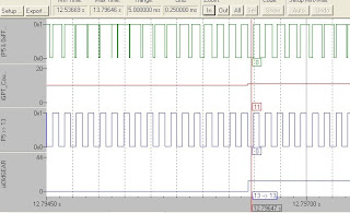
After compiling the project, I run the debugger and open the Logic Analyzer window to show the input signals and the internal variables. Here what happen after 12.79s of execution: the uiGEAR value is 11 indicating that the 6th gear is inserted:

With the following frequencies:
- P5.13 for front weel = 8800Hz (= 109KM/h)
- P5.12 for rear weel = 8400Hz (= 109KM/h)
- P3.7 for the engine = 117Hz (= 7000 RPM).
After running again the debugger, the Logic Analyzer shows (after 12.79s of execution): the uiGEAR value is 13 indicating that the 5th gear is inserted:


For the time being that's all, next step will be to add teh CAN node and transmit the measured and calculated values to dash-board....

Monday, December 8, 2008

First Project (the simplest!)


My aim is to develop an ECU dedicated to control the intake air system ram.


Short air rams allow fast intake, while long air rams allow slow air wave.
Yamaha with its YCC-I, now available on R1 and R6, controls the air rams lenghts.
As example, some R1 engine tests show:
- long rams: at high regimes the output power would be reduced to 145,1 CV (at 10.250 rpm), while at lower regimes it is increased
- short rams: above 10.000 rpm the output power is increased to 160 CV (at 10.250 rpm)


Thenrefore I need a dedicated ECU able to:
1. acquire the current engine speed
2. acquire the throttle position
3. control a servo-motor to move the air rams


Since nowadays ECUs have CAN bus, for tasks 1 and 2, I plan to get the engine rotation speed (rpm) and throttle position by CAN messages. Therefore the only task to be performed by MaxECU is to control the servo-motor. After some internet searches, I got the idea to reuse a standard and robust servo-motor: the one used for RC models!


MaxECU system description:
- XC164CM from Infineon, 16-bit CPU and various peripherals (see http://www.ehitex.de/p_info.php?xPD=113_117&products_id=264)
- 2xCAN nodes
- 1xADC channel (in case the throttle position is not available via CAN message)
- 1xDigital Input (in case RPM is not available via CAN message)
- 1xDigital Output (PWM) to drive the servo-motor position


Software:


the project is quite simple, infact the XC164CM is providing several peripherals to easy the task.


RPM meter:


in order to acquire the engine rotating speed, it is necessary to allocate one timer and a counter connected to the Digital Input. I use the RTC-T14 (timer 14) to generate a 1sec timebase, at each generated interrupts (every second) the counter T6 is latch, reset and restarted for the next acquisition. Mainly there is no CPU load to perform such operations, here the Interrupt Service Routine example:


GPT2_vStopTmr(GPT2_TIMER_6);
// Read T6 Counter content and save in global variable
uiRPM_REAR = GPT2_uwReadTmr(GPT2_TIMER_6);
// Clear T6
GPT2_vClearTmr(GPT2_TIMER_6);
GPT2_vStartTmr(GPT2_TIMER_6);


where the global variable "uiRPM_REAR" contains the latest acquired engine rotation speed. Since our bike has already an ECU, it is fairly simple to get access to the "RPM signal", on Yamaha R6 is available on ECU cabling.


Servo-motor control:
a servo-motor for RC models is very simple to be controlled. In fact, it has a 3 wire cable as:


where the position is controlled by the pulse width on the signal cable:


the relationship between pulse width to rotor position is quite easy:
- 1.0 msec <-> 0% position
- 1.5 msec <-> 50% position
- 2.0 msec <-> 100% position (where position could be 180 ° or less depending on the servo-motor model. See: http://www.futaba-rc.com/servos/digitalservos.html)

To generate such waveforms, I have used 2 timers: T3 and T4. T3 is used for the 10 usec timebase, while T4 is used for generating the delay between consecutive pulses. Software is quite simple:


iPosition = 50; // x% of Zero position
GPT12E_T4= T4_15ms;

while (1) {
// Start only if Timer T4 gives the signal
if (bStartPulseModulation == 0xF)
{
bStartPulseModulation = 0;
// Pulse starts with 1msec HIGH signal even if iPosition = 0%
P1L_P0 = 1; // DIO1 == P1L.0 = HIGH for 1msec
GPT1_Wait(T3_1ms); // Wait 1msec

// Enlarge the pulse time depending on iPosition
if ( iPosition != 0)
{
cnt = (iPosition * 50) - 1;
GPT1_Wait(cnt);
}

// Pulse LOW: Stop !
P1L_P0 = 0; // DIO1 == P1L.0 = LOW
}
}

The output waveforms are:


Sunday, December 7, 2008

The Bike


Yamaha R6 (M.Y. 2003)

Filtro by BMC
Scarico by Arrow titanio 4-2-1 con terminale in carbonio
Candele by NGK iridio
Monoammortizzatore by Ohlins TTX
Forcelle by Josué
PowerCommander by Ferracci
Contamarce by GPR
Tubi Freno by Frentubo
Pedane e manettini regolazione forcelle by 4-racing
Trasmissione by DID Racing
Condotti Airbox in carbonio by VTRMOTO
Tappo serbatoio by ValterMoto


Intro

Hallo to all,

I decided to open a public Blog on self made Electronic Control Units (ECUs). My goal is to publish my experiments and results in order to keep trace of my own projects and to get the contribution of everyone.

Get fun and feedback me !