XE164 has to acquire, measure and sincronize to the INJ-in signals (one for each motorbike injectors).
The best way is to use a dedicated XE164 peripheral: the CAPCOM2 unit.
The CAPCOM unit is designed for capturing, measuring various signals in respect to a base timer. The idea is the following:
- a timer is resetted and started once necessary (TIMER7)
- various I/O port signals can be used to capture the timer value at the signal trigger.
Since the same I/O port signal can be used on various capturing units, MaxPowerCMD will:
- INJ-in rising edge is used to capture the delay between the 0 degree and the injection firing time (let's call t1)
- INJ-in falling edge is used to capture the time when the motorbike ECU likes to stop the injection pulse (let's call t2)
Therefore it will be possible to calculate the injection pulsewidth by subtracting t2 from t1, D=t2-t1.
Once the pulsewidth has been calculated, the CAPCOM timer can be reset, so to be ready for the incoming capturing phase.
To configure properly the XE164's CAPCOM is only necessary to estimate correctly the timing scale that the injector events require.
Supposing that the motorbike engine runs at 10000 RPM as max speed, so each injector will fire every 10000/60 Hz, so about 166Hz.
The second parameter to be considered is the measurement accurancy: each injection pulse could be around 2msec, so at least a precision of 0.1msec is required.
0.1 msec x 65535 = 6553.5msec is far enough.
Sunday, December 13, 2009
Tuesday, December 1, 2009
MaxPowerCMD: the logic gates
As anticipated, the logic gates have been added between the motorbike ECU Injector signal to the replicated Injector driver.

I have defined it by defining the transfer function table, as:

Once the transfer function have been fully defined, it is now possible to give some examples.
Example 1: Injection Pulsewidth enlargement
In this case, the XE164 will set EN='1' just before that the real motorbike Injection signal will come (called INJ-in in the above table). In this way, the logic gates will act as a pass gate transferring the INJ-in signal to the output (OUT signal). The MaxPowerCMD power MOS will then drive the injector solenoid to lift the pintle. So, exactly following the motorbike ECU imposed sequene without any delay.
Now XE164 can recognize and sincronize the motorbike intention by acquiring the status of INJ-in signal (INJ-in='1' at Time=1). The XE164 knowns the pulsewith from the previous injection cycle and then it will access the Alpha-N table and retrieve the percentage to enlarge or decrease the current injection pulsewidth. XE164 sets the EN='1' so to be sure that even if the motorbike pulse disappear, the OUT will stay high. At this point the XE164 set-up the related timer designed to drive low the EN signal at the righ time (Time = 5).
All the above is depicted in the following plot, from Time = 0 to Time = 6:

Example 2: Injection Pulsewidth shortening
Similar to the above example 1, whenever XE164 needs to shorten the Injector pulsewidth, it can act as depicted from Time = 7 to 12.
Example 3: Injection Pulsewidth anticipation
Similar to the above example 1, whenever XE164 needs to anticipate the Injector pulsewidth, it can act as depicted from Time = 13 to 18. Please note that this operation can be really dangerous for the engine functionality since it could lead to wrong detonation or other bad sideeffcts.
So, to summarize, the logic gates is needed to change the Injection Pulsewidth:

I have defined it by defining the transfer function table, as:
Once the transfer function have been fully defined, it is now possible to give some examples.
Example 1: Injection Pulsewidth enlargement
In this case, the XE164 will set EN='1' just before that the real motorbike Injection signal will come (called INJ-in in the above table). In this way, the logic gates will act as a pass gate transferring the INJ-in signal to the output (OUT signal). The MaxPowerCMD power MOS will then drive the injector solenoid to lift the pintle. So, exactly following the motorbike ECU imposed sequene without any delay.
Now XE164 can recognize and sincronize the motorbike intention by acquiring the status of INJ-in signal (INJ-in='1' at Time=1). The XE164 knowns the pulsewith from the previous injection cycle and then it will access the Alpha-N table and retrieve the percentage to enlarge or decrease the current injection pulsewidth. XE164 sets the EN='1' so to be sure that even if the motorbike pulse disappear, the OUT will stay high. At this point the XE164 set-up the related timer designed to drive low the EN signal at the righ time (Time = 5).
All the above is depicted in the following plot, from Time = 0 to Time = 6:
Example 2: Injection Pulsewidth shortening
Similar to the above example 1, whenever XE164 needs to shorten the Injector pulsewidth, it can act as depicted from Time = 7 to 12.
Example 3: Injection Pulsewidth anticipation
Similar to the above example 1, whenever XE164 needs to anticipate the Injector pulsewidth, it can act as depicted from Time = 13 to 18. Please note that this operation can be really dangerous for the engine functionality since it could lead to wrong detonation or other bad sideeffcts.
So, to summarize, the logic gates is needed to change the Injection Pulsewidth:
- EN is used to shortening or postpone it
- ON is used to enlarge or anticipate it
Monday, November 30, 2009
Engine Management: Ignition Primary Circuits
Before starting the real Injection system, is important to understand what is key and important to know.
Let's start from the Aprilia Caponord ECU Injection system:

Therefore each injection coil is connected to +12V directly and grounded via the ECU circuit, the ECU Injector driver circuit looks like this:

The above picture represent a simple ECU circuit to drive the Fuel Injector. In essence, the ECU (the XE164 in the case of MaxPowerCMD) drives the first BJT transistor that acts as a voltage buffer to being able to drive the power MOS with higher voltages than the uC power supply (Aprilia RSV1000 Injector driver circuit is visible at Randomexploits).
Fuel Injectors
Let's copy some useful description of Fuel Injectors (or from Wiki).

Note that the solenoid voltage increases up to about 60V after the power MOS is turned off (as a result of the constant elettro-magnetic field).

Note that the injector solenoid current is quite low, about 0.6A (Mr. Jefferies MyECU declares 1 - 2 A per injector)
Wiki documentation claims that
The above voltage / current measurement scopes are showing a 4msec injection pulsewidth.
In my project MaxPowerCMD is not important to learn how to calculate the Fuel Injection pulsewidth since this is done by the motorbike ECU hardware. The motorbike ECU will feed the MaxPowerCMD with the desired Fuel Injection pulsewidth, but MaxPowerCMD will drive the Injector by changing the injection pulse, as for example:
- motorbike ECU pulsewidth = 5 msec
==> MaxPowerCMD [RPM, trottle, gear, ...] = 110%
==> MapowerCMD will drive a 5.5msec injection pulse
... and so on...
I think now is more clear what has to be done in software by using the powerful XE164 System on Chip.
Let's start from the Aprilia Caponord ECU Injection system:

Therefore each injection coil is connected to +12V directly and grounded via the ECU circuit, the ECU Injector driver circuit looks like this:

The above picture represent a simple ECU circuit to drive the Fuel Injector. In essence, the ECU (the XE164 in the case of MaxPowerCMD) drives the first BJT transistor that acts as a voltage buffer to being able to drive the power MOS with higher voltages than the uC power supply (Aprilia RSV1000 Injector driver circuit is visible at Randomexploits).
Fuel Injectors
Let's copy some useful description of Fuel Injectors (or from Wiki).
The injector is an electromechanical device, which is fed by a 12 volt supply from either the fuel injection relay or the ECM. The injector is supplied with fuel from a common fuel rail. The injector pulse width depends on the input signals seen by the ECM from its various engine sensors, and varies to compensate for cold engine starting and warm-up periods, the initial wide pulse getting narrower as the engine warms to operating temperature. The pulse width also expands under acceleration and contracts under light load conditions. The injector has constant voltage supply while the engine is running and the earth path is switched via the ECM. An example of a typical voltage waveform is shown below in:
Note that the solenoid voltage increases up to about 60V after the power MOS is turned off (as a result of the constant elettro-magnetic field).
Is then easy to understand that every time that ECU drives a current trough the injector solenoid, after an initial set-up time, a fuel injection will occur, as visible in: fuel injection animation.
An electromechanical injector of course takes a short time to react, as it requires a level of magnetism to build before the pintle is lifted off its seat. This time is called the ‘solenoid reaction time’. This delay is important to monitor and can sometimes occupy a third of the total pulse width. A good example of the delay in opening can be seen in the example waveform shown below:
Note that the injector solenoid current is quite low, about 0.6A (Mr. Jefferies MyECU declares 1 - 2 A per injector)
The waveform is ‘split’ into two clearly defined areas. The first part of the waveform is responsible for the electromagnetic force lifting the pintle, in this example taking approximately 0.6 ms. At this point the current can be seen to level off before rising again as the pintle is held open. With this level off ind it can be seen that the amount of time that the injector is held open is not necessarily the same as the time measured. It is not however possible to calculate the time taken for the injector’s spring to fully close the injector and cut off the fuel flow.
Wiki documentation claims that
Injector pulsewidth typically ranges from 4 ms/engine-cycle at idle, to 35 ms per engine-cycle at wide-open throttle. The pulsewidth accuracy is approximately 0.01 ms.
The above voltage / current measurement scopes are showing a 4msec injection pulsewidth.
In my project MaxPowerCMD is not important to learn how to calculate the Fuel Injection pulsewidth since this is done by the motorbike ECU hardware. The motorbike ECU will feed the MaxPowerCMD with the desired Fuel Injection pulsewidth, but MaxPowerCMD will drive the Injector by changing the injection pulse, as for example:
- motorbike ECU pulsewidth = 5 msec
==> MaxPowerCMD [RPM, trottle, gear, ...] = 110%
==> MapowerCMD will drive a 5.5msec injection pulse
... and so on...
I think now is more clear what has to be done in software by using the powerful XE164 System on Chip.
Saturday, November 28, 2009
MaxPowerCMD
Since my old Caponord need some "power injection" and that in any case the Traction Control need engine power adaptation, I thought is time to design my own Power Cmd.
The basic idea is to build up an electronic system to be connected at ECU inputs (trottle position, engine RPM, engine speed, ...) and outputs (injector driving signals, ...) so to change the injections maps during engine operation.
To clarify my initial ideas, I draw this:

So, let's try to explayin (and clarify myself also):
- on the left there is the original Motorbyke ECU, one Injector channel is drawn only. The Aprilia Caponord ECU drives the 4 Injectors exactly in such way: each Injector is connectd to +12V and the low side is switched by ECU (most likely using a power N-MOS), this is what I found from original Aprilia manual:
- between the fuel Injector (drawn on top right) a "fake injector" is inserted: this is needed to scope the Injector signal and to make sure that the ECU sense something and believes that Injector is still connected and working as expected:

- some logic gates must be inserted so to be able to replicate the original ECU signal as it is or to modify it:
- the last blocks is the MaxPowerCMD CPU itself, so the XE164:
 .
.
How it works?
The basic idea is the following:
1- MaxPowerCMD has to sense the time when the motorbyke ECU would like to start an Injection sequence
2- MaxPowerCMD has to sense the Injector ON time at every revolution
==> with all information from 1 and 2, MaxPowerCMD would be able to reproduce the same Injection pulse as the motorbyke ECU would do
3- MaxPowerCMD has to measure the engine RPM
4- MaxPowerCMD has to measure the trottle position
==> with all information from 3 and 4, MaxPowerCMD would be able to access to a new Injection MAP as:

==> the Injection MAP will have to be designed in % way, so 100% would indicate that the MaxPowerCMD will not change the motorbyke Injector pulse width. 50% would indicate a 50% shorter pulse and 150% an 1+1/2 pulse lenght. From this last requirement is now easy to understand why I have designed the logic gate block
to èermit to create an output signal that is shorter or longer then the ECU's imposed. The logic gate implementation also simplify the need to sincronize the MaxPowerCMD with the ECU signals since the MaxPowerCMD will simply impose the BYPASS mode just before any new injection sequence.
Before proceeding with the MaxPowerCMD I think is better to acquire more information about the Aprilia Caponord electronic injection system.
Injectors Test:
Aprilia indicated that a working Injector should have a resistence of about: 11,5 - 13 Ω at 20 °C (68 °F):

The basic idea is to build up an electronic system to be connected at ECU inputs (trottle position, engine RPM, engine speed, ...) and outputs (injector driving signals, ...) so to change the injections maps during engine operation.
To clarify my initial ideas, I draw this:

So, let's try to explayin (and clarify myself also):
- on the left there is the original Motorbyke ECU, one Injector channel is drawn only. The Aprilia Caponord ECU drives the 4 Injectors exactly in such way: each Injector is connectd to +12V and the low side is switched by ECU (most likely using a power N-MOS), this is what I found from original Aprilia manual:
- between the fuel Injector (drawn on top right) a "fake injector" is inserted: this is needed to scope the Injector signal and to make sure that the ECU sense something and believes that Injector is still connected and working as expected:

- some logic gates must be inserted so to be able to replicate the original ECU signal as it is or to modify it:
- the last blocks is the MaxPowerCMD CPU itself, so the XE164:
 .
.How it works?
The basic idea is the following:
1- MaxPowerCMD has to sense the time when the motorbyke ECU would like to start an Injection sequence
2- MaxPowerCMD has to sense the Injector ON time at every revolution
==> with all information from 1 and 2, MaxPowerCMD would be able to reproduce the same Injection pulse as the motorbyke ECU would do
3- MaxPowerCMD has to measure the engine RPM
4- MaxPowerCMD has to measure the trottle position
==> with all information from 3 and 4, MaxPowerCMD would be able to access to a new Injection MAP as:

(rows: trottle position; columns: engine RPM speed)
==> the Injection MAP will have to be designed in % way, so 100% would indicate that the MaxPowerCMD will not change the motorbyke Injector pulse width. 50% would indicate a 50% shorter pulse and 150% an 1+1/2 pulse lenght. From this last requirement is now easy to understand why I have designed the logic gate block
to èermit to create an output signal that is shorter or longer then the ECU's imposed. The logic gate implementation also simplify the need to sincronize the MaxPowerCMD with the ECU signals since the MaxPowerCMD will simply impose the BYPASS mode just before any new injection sequence.
Before proceeding with the MaxPowerCMD I think is better to acquire more information about the Aprilia Caponord electronic injection system.
Injectors Test:
Aprilia indicated that a working Injector should have a resistence of about: 11,5 - 13 Ω at 20 °C (68 °F):

Sunday, September 13, 2009
First Project (the simplest!) - Part 2
After a long time I restarted playing with servomotors to control the intake air system ram. Here my latest achievements with servo motors:
Stai tuned....
Saturday, May 9, 2009
Weeling Display goes to PCB
It's time now to create a real PCB for the Weeling Display, so everyone of you could create his own Weeling Traction Control.
First of all, if you do not know, just have a look to the old posts:
Display It!
Display It! (Cont...)
Display It! (Cont...)
XE164 to Display connections
After the debug and the "in circuit" test, I drawn the schematic using Eagle (Eagle 5.5.0), here you can see it:

the above is the version with 9 displays in order to monitor:
- Gear (it's the display in the middle and it's a bigger model)
- Engine RPM or Speed
- Oil Temperature or Weeling Percentage (how much the rear weel is spinning in percentage)
Using the freeware Eagle version, is not possible to route a so big display, so I have reduced to 7 Displays and reoute as follows:

here the bottom Layer:

here the top Layer:

Component side is:

Component List:
Currently I'm trying to build my first PCB, pictures will come soon...
First of all, if you do not know, just have a look to the old posts:
Display It!
Display It! (Cont...)
Display It! (Cont...)
XE164 to Display connections
After the debug and the "in circuit" test, I drawn the schematic using Eagle (Eagle 5.5.0), here you can see it:

the above is the version with 9 displays in order to monitor:
- Gear (it's the display in the middle and it's a bigger model)
- Engine RPM or Speed
- Oil Temperature or Weeling Percentage (how much the rear weel is spinning in percentage)
Using the freeware Eagle version, is not possible to route a so big display, so I have reduced to 7 Displays and reoute as follows:

here the bottom Layer:

here the top Layer:

Component side is:

Component List:
Exported from WeelingDsiplay.sch at 5/2/2009 5:07:31 PM
EAGLE Version 5.5.0 Copyright (c) 1988-2009 CadSoft
Part Value Device Package Library Sheet
C1 100uF 25V
C2 100uF 10V
DIS1 HD-H103
DIS2 HD-H103
DIS3 HD-H103
DIS4 HD-H103
DIS5 HD-H103
DIS6 HD-H103
DIS7 HD-H103
DIS8 HD-H103
GEAR HD-N103 display-hp
IC1 4511N
IC2 7805
POWER 12V
R-D 330 ohm
R1 330 ohm
R2 330 ohm
R3 330 ohm
R4 330 ohm
R5 330 ohm
R6 330 ohm
R7 330 ohm
R8 330 ohm
R9 330 ohm
R17 330 ohm
R18 330 ohm
R19 330 ohm
R20 330 ohm
R21 330 ohm
R_A 330 ohm
R_B 330 ohm
R_C 330 ohm
R_E 330 ohm
R_F 330 ohm
R_G 330 ohm
T1 BC373-NPN-TO92
T2 BC373-NPN-TO92
T3 BC373-NPN-TO92
T4 BC373-NPN-TO92
T5 BC373-NPN-TO92
T6 BC373-NPN-TO92
T7 BC373-NPN-TO92
T8 BC373-NPN-TO92
T_GEAR BC373-NPN-TO92-CBE TO92-CBE transistor 1
X1 2520- 2520- PAK100/2500-20 con-3m 1
Currently I'm trying to build my first PCB, pictures will come soon...
Friday, May 1, 2009


Friday, April 17, 2009
Traction Control Connections
Weeling in mounted on my Yamaha R6, I still have to decide how to operate the Traction Control and how to connect it to the byke ECU.
Thinking and rethinking I had the idea to connect the traction control as the Electronic Shift units are doing. I found the following instructions:

so, if I have correctly understood the idea is to cut the power supply of the fuel injectors or of the spark coils.
Some friend told me that avoiding the spark firing could be that the spark get wet and therefore damaged... not really nice!!! Most likely is better to interrupt the fuel Injection.
From the R6 manual (2003 model), I have extracted the following electrical circuit:

(where "12" is the POWER SUPPLY RELAY and "18" are the fuel injectors).
The idea could be to use an HV P-MOS transistor and turn off the power supply of the fuel injectors as:

The driver circuit could look like:

Someone have some idea or suggestions?
Friday, April 10, 2009
Yamaha R6 (2003 Model) Water Temperature Sensor
Finally I was able to connect my "Welling" to the Yamaha R6 (2003 model) ECU in order to acquire the water temperature.
I explayin how to do, looking to the Yamaha R6 electrical circuit manual, the water temperasture sensor (#23 in the picture) is directly connected to the ECU:

Therefore is quite simple to connect it: just take a cable and solder it on the ECU connector G/W (Green/White- mainly is a green cable with a little white stripe) cable, bring it to the XE164 KeyChain and compute the temperature as:
I've used such equation since I have desumed from the Yamaha manual the following NTC curve (it declares that the NTC has 6.37KOhm at 0°C and 0.35kOhm at 80°C):
 Temperature Vs. NTC resistance
The same could be plotted as Temperature Vs. ADC Voltage
 Temperature Vs. ADC Voltage
Looking to the same, but plotting Temperature Vs. ADC value in the range 60°C .. 110°C (the most important temperature range), we get:
 Temperature Vs. ADC value
and this is what I measured:

After a little rearrangement, I fit it better:

Now I calculate the SLOPE and the INTERCEPT (I assume a linear equation to have a simple calculation):
SLOPE = -1.32
INTERCEPT = 127.42
I explayin how to do, looking to the Yamaha R6 electrical circuit manual, the water temperasture sensor (#23 in the picture) is directly connected to the ECU:

Therefore is quite simple to connect it: just take a cable and solder it on the ECU connector G/W (Green/White- mainly is a green cable with a little white stripe) cable, bring it to the XE164 KeyChain and compute the temperature as:
uiTmp = (unsigned int) ( ((float) ( uiTemperature >> 4) ) * (-1.32) + 127.42 )
/*
uiTemperature is the 12-bit ADC converted values, before temperature calculation I reduce the precision to have stable temperature visualization (I do not need so high precision)
*/
I've used such equation since I have desumed from the Yamaha manual the following NTC curve (it declares that the NTC has 6.37KOhm at 0°C and 0.35kOhm at 80°C):
 Temperature Vs. NTC resistance
The same could be plotted as Temperature Vs. ADC Voltage
 Temperature Vs. ADC Voltage
Looking to the same, but plotting Temperature Vs. ADC value in the range 60°C .. 110°C (the most important temperature range), we get:
 Temperature Vs. ADC value
and this is what I measured:

After a little rearrangement, I fit it better:

Now I calculate the SLOPE and the INTERCEPT (I assume a linear equation to have a simple calculation):
SLOPE = -1.32
INTERCEPT = 127.42
Thursday, April 2, 2009
Traction Control Settings (Con't)

As promised, here it comes the debug... So, the only bug I discover was that in my calculation I have used 10-bit ADC resolution, but in reality the XE164 has 12-bit resolution (from 0 to 4095), so the only modification I did was to shift the value as:
uiTmp = ( ADC1_RESRA0 >> 2 ); // Get latest Manettino valueMoreover I have added a piece of code to show on display the TC settings, the meaning is:
 At the end the weeling electronics in its little box is:
Wednesday, April 1, 2009
Traction Control Settings
As you can immagine, I'm continuosly thinking on how to tune the Traction Control (TC). One idea could be to flash some key parameters or to control it more easily. Looking around I've seen this very interesting solution:

I like since seems user frendly... I try to go for it!
Step 1
first is to select the adjustment switch: I go for a 10K potentiometer since it is cheap and I think it ca do all what I need. In order to give fashion to it, I like to call it as "MANETTINO" like Ferrari does for a similar stuff they have on the dashboard (by the way, manettino means "tiny handle").
Step 2
I try to define what I really need: I like to be able to change the TC threshold (I mean when it starts to work) and the sensibility (I mean how much strongly reduces the engine tourque).
Step 3
Potentiometer working definition:
- each 40° of potentiometer revolution I like to change the TC threshold as:

Fig.1) depending on manettino position, the potentiometer output voltage is changed from 0V to 5V corresponding to OFF, 110%, 120%, 130%, 140%, 150% and 160% threshold factors.
- inside each 40° of potentiometer revolution I like to modulate the TC sensitivity giving a progressive change in both sensitivity:

Fig.2) depending on manettino position, the TC threshold is changed from OFF, 110%, 120%, 130%, 140%, 150% and 160%. Once the threshold is selected, the sensibility can be adjusted from 0 to 1
Step 4
The circuit to be added is quite easy: I add just one potentiometer from 5V to GND, the cursor is connected to the ADC_1 channel 0.
Step 5
Off-line calculation: in order to write the software I need to write down all the variables and try to build up a model: I use a spreadsheet - what else!
This is what I generate, I know is not so easy to understand, but it shows how the manettino position is converted to voltage and to ADC value and then to TC threshold and TC sensitivity:

Step 6
Now is time to think about the software changes. First I need a couple of new static variables:
- uiTC_Threshold
- uiTC_Slope
and then I need to configure the ADC_2 for cntinuous conversions, I use DAvE as usual:

I like to limit the "manettino" changes only when the bike is not running, therefore, in the OFF state I add the following lines:
Step 7
I need now another timer to modulate the engine tourque as calculated by the TC, I use Timer_7 from the CC2 unit:

The selected resolution is 15.515 usec, therefore to conver the ADC value into timer counter value, I just need to multiply by 432:
The last stuff is to toggle port P10.7: the software turns it on, the Timer 7 Interrupt Service Routine turns it off:
Step 8
well, last step is to test it! I'll do tomorrow...
Step 1
first is to select the adjustment switch: I go for a 10K potentiometer since it is cheap and I think it ca do all what I need. In order to give fashion to it, I like to call it as "MANETTINO" like Ferrari does for a similar stuff they have on the dashboard (by the way, manettino means "tiny handle").
Step 2
I try to define what I really need: I like to be able to change the TC threshold (I mean when it starts to work) and the sensibility (I mean how much strongly reduces the engine tourque).
Step 3
Potentiometer working definition:
- each 40° of potentiometer revolution I like to change the TC threshold as:

- inside each 40° of potentiometer revolution I like to modulate the TC sensitivity giving a progressive change in both sensitivity:

Step 4
The circuit to be added is quite easy: I add just one potentiometer from 5V to GND, the cursor is connected to the ADC_1 channel 0.
Step 5
Off-line calculation: in order to write the software I need to write down all the variables and try to build up a model: I use a spreadsheet - what else!
This is what I generate, I know is not so easy to understand, but it shows how the manettino position is converted to voltage and to ADC value and then to TC threshold and TC sensitivity:

Step 6
Now is time to think about the software changes. First I need a couple of new static variables:
- uiTC_Threshold
- uiTC_Slope
and then I need to configure the ADC_2 for cntinuous conversions, I use DAvE as usual:

I like to limit the "manettino" changes only when the bike is not running, therefore, in the OFF state I add the following lines:
uiTmp = ADC1_RESRA0; // Get latest Manettino value
if ( uiTmp > 150 )
{
uiTC_Threshold = 1000 + ((unsigned int)( uiTmp / 151 ) * 100); // 110% is 0.74V
uiTC_Slope = ( uiTmp % 151 ); // Remainder
} else {
uiTC_Threshold = 0;
uiTC_Slope = 0;
}
Step 7
I need now another timer to modulate the engine tourque as calculated by the TC, I use Timer_7 from the CC2 unit:

The selected resolution is 15.515 usec, therefore to conver the ADC value into timer counter value, I just need to multiply by 432:
// Traction Control Timer Calculation
CC2_vLoadTmr ( CC2_TIMER_7, uiTC_Slope*432 );
The last stuff is to toggle port P10.7: the software turns it on, the Timer 7 Interrupt Service Routine turns it off:
IO_vSetPin( IO_P10_7 ); // TC-OFF to HIGH
...
void CC2_viTmr7(void) interrupt CC2_T7INT
{
// TC-OFF signal to LOW after timer expires
IO_vResetPin( IO_P10_7 ); // TC-OFF to LOW
} // End of function CC2_viTmr7
Step 8
well, last step is to test it! I'll do tomorrow...
Tuesday, March 31, 2009
Accellerometers and traction control
As my friend Fabio suggested, I should include some accellerator sensors to better perform the traction control.
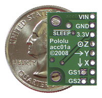
The task should not so difficult since there are many accellerometers on the market even for low prices. In particular, I think is better to look at those having a digital interface (i.e. IIC2 or SPI bus) instead of those having pure analogue output. Looking around I've found many but all have tiny pacheages so are really difficult to be soldered! Thanks to FuturaElettronica we can get a soldered 3-axis accellerometer for only 13€: link.
How it works?
The digital accellerometers are MEMS componenet having one floating part inside that goes to change 3 capacitances (each capacitor is perpendicular to each other: one in X direction, one in Y and one in Z), the capacitance variation are then converted to digital signals by appropriate circuitry integrated on the same die. Typically they could measure +/-1.5g or +/-6g, but for the byke the +/-2g should be enough, so the MMA7455LT could be ok.
Monday, March 30, 2009
XE164 KeyChain ERRATA
Please take care that the KeyChain serigraphy of connector J4 is wrong: pin P04 is bottom-right and not top-left. the following picture try to explayin it:


Saturday, March 28, 2009
How works CDI
Since I need to modulate the engine power, I need to understand the CDI technology:
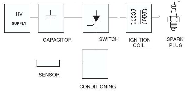
Capacitor
The Capacitor is the main component: in the fist phase it is charged whle in the second phase it is discharged trought the coil and the spark. Typically is value is from 0.47uF to 2µF .
Switch
The Switch element has the purpose to transfer the energy from the capacitor to the coil, typically it is composed of one SCR ( Silicon Controlled Rectifier) or TRIAC combined with one diode for the reverse current coming from the ignition coil.
Ignition coil
The ignition coil has the goal to increase the voltage to 5 .. 20 kV
Spark plug
The Spark is such component capable to fire the combustible mixtures. The mixutures could start burning only if about 20 milli joules will be given to it.
Finally also a position sensor and an CPU is required:
Let's try to understand the hot part:
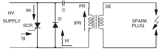
Seems that when the SCR start to be conductive, the current Ith goes from the capacitor to the coil, while the negative impulse is conducted by the diode. Finally the current that goes into the coil is:
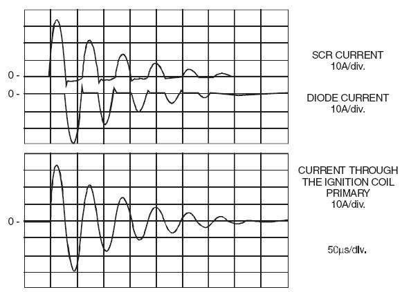
Uhmmm.... this is not all what I would need to fully understand it, but is a good starting point!
Capacitor
The Capacitor is the main component: in the fist phase it is charged whle in the second phase it is discharged trought the coil and the spark. Typically is value is from 0.47uF to 2µF .
Switch
The Switch element has the purpose to transfer the energy from the capacitor to the coil, typically it is composed of one SCR ( Silicon Controlled Rectifier) or TRIAC combined with one diode for the reverse current coming from the ignition coil.
Ignition coil
The ignition coil has the goal to increase the voltage to 5 .. 20 kV
Spark plug
The Spark is such component capable to fire the combustible mixtures. The mixutures could start burning only if about 20 milli joules will be given to it.
Finally also a position sensor and an CPU is required:
Let's try to understand the hot part:
Seems that when the SCR start to be conductive, the current Ith goes from the capacitor to the coil, while the negative impulse is conducted by the diode. Finally the current that goes into the coil is:
Uhmmm.... this is not all what I would need to fully understand it, but is a good starting point!
Sito segnalato da: La risorsa Italiana per l'elettronica. |
Friday, March 27, 2009
Traction Control (Con't)
I did some researches in vision of the traction control: I look for POWER MOS capable to sustain high voltages....
Here what I found (and get!!!):
1. IPB50N10S3L-16
2. IPD50P03P4L-11
Humm, not really useful for the CDI, the best would be to get:
* IPP60R099CPA
* IPP60R099CP available from Farnell
... I think I should order from Farnel...
Here what I found (and get!!!):
1. IPB50N10S3L-16
2. IPD50P03P4L-11
Humm, not really useful for the CDI, the best would be to get:
* IPP60R099CPA
* IPP60R099CP available from Farnell
... I think I should order from Farnel...
Sunday, March 22, 2009
Weeling Project goes to Traction Control
Since the Weeling Project is now working, I like to extend it with the Traction Control feature.
The basic idea is to cut the torque each time the rear weel is spinning above a certain threshold (same threshold used for the blinking white LED).
I've done some researches and I found out that one idea could to reduce the engine torque is to cut one cilinder spark firing.
Let's start to understand how Yamaha R6 is working:

About the spark coil, I found:


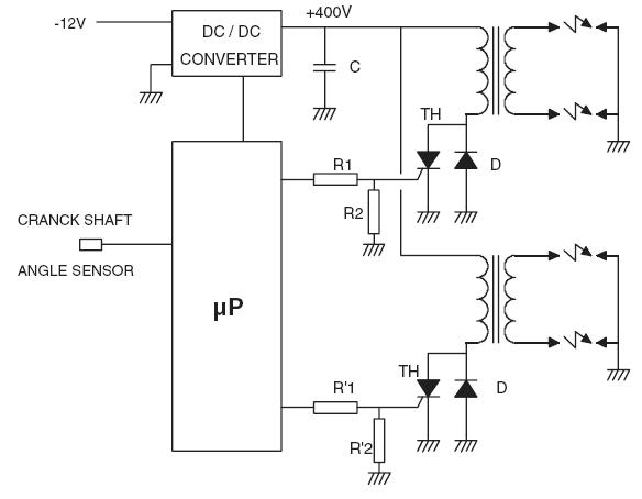
Yamaha declare to use a CDI, this is what Wiki is teaching us:
The circuit shuld be similar to the B-type:

threfore without additional information, I have to assume that inside the Yamaha R6 ECU four capacitors are available and charged at about 400V and ready to share their energy with the spark-coils (E = 0.5 x L x I2 = 0.5 x C x V2) when the fire should happen.
Tourque Control
One idea to control the tourque seems to be the disabling of one cilinder firing, seems that GripOne is implementing such strategy.
Looking around I found this connection for the Inductive Transistorized injection (so, not working on my R6):

Some useful links:
McLaren CDI
GripOne Manual
The basic idea is to cut the torque each time the rear weel is spinning above a certain threshold (same threshold used for the blinking white LED).
I've done some researches and I found out that one idea could to reduce the engine torque is to cut one cilinder spark firing.
Let's start to understand how Yamaha R6 is working:

About the spark coil, I found:


Yamaha declare to use a CDI, this is what Wiki is teaching us:
In a CDI system, a charging circuit charges a high voltage capacitor, and during the ignition point the system stops charging the capacitor, allowing the capacitor to discharge its output to the ignition coil before reaching the spark plug.
A typical CDI module consists of a small transformer, a charging circuit, a triggering circuit and a main capacitor. First, the system voltage is raised up to 400-600 V by a transformer inside the CDI module. Then, the electric current flows to the charging circuit and charges the capacitor. The rectifier inside the charging circuit prevents capacitor discharge before the ignition point. When the triggering circuit receives triggering signals, the triggering circuit stops the operation of the charging circuit, allowing the capacitor to discharge its output rapidly to the low inductance ignition coil, which increase the 400-600 V capacitor discharge to up to 40 kV at the secondary winding at the spark plug. When there's no triggering signal, the charging circuit is re-connected to charge back the capacitor.
The circuit shuld be similar to the B-type:
threfore without additional information, I have to assume that inside the Yamaha R6 ECU four capacitors are available and charged at about 400V and ready to share their energy with the spark-coils (E = 0.5 x L x I2 = 0.5 x C x V2) when the fire should happen.
Tourque Control
One idea to control the tourque seems to be the disabling of one cilinder firing, seems that GripOne is implementing such strategy.
Looking around I found this connection for the Inductive Transistorized injection (so, not working on my R6):

Some useful links:
McLaren CDI
GripOne Manual
Subscribe to:
Posts (Atom)