I look around and I found the following proposed circuit:

(taken from FiserTek ).
As you can see, the circuit is quite simple: there is only one BCD to 7-segment driver (the famous HC4511, HC4511) connected in parallel to several 7-segment displays (the schematic just shows 4 of it, but I connected 6, and more could be connected). Each 7-segment display (displays must be common Kathode) are enabled by the T1, T2, ... BC337 transistors driven from the SV3 signals (CPU outputs).
In my Weeling Project, I need 6 digits:
- 4 digits for distance meter (odometer): RED colour
- 2 digits for cooling water temperature: GREEN colour

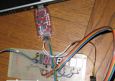
As you can see from the picture, I had no time to create an own pcb, instead I use multi-purpose pcb and I solder it using tiny wires (I know is not nice...).
So, the total amount of CPU ouputs are:
- 4 outputs for driving the BCD digit (SV1 connector)
- 6 outputs for driving the respective BC337 transistors
The 4 RED digits can be used for the distance meter if the bike speed is below 5 KM/h (so, every time the Weeling Status is "IDLE"), or for Gear indication if speed is above. Please note that due to the BC337 transistors, the hardware is so flexible to permit CPU to drive not all displays: so is possible to keep off some digits if not needed in some conditions (i.e. is not needed to see the distance meter during the ride, it is more important to display other information).
After soldering and a simple debug (no issues found!), I develop the CPU software to drive it. It is quite simple, it just needs to:
- configure the neededs ports as outputs
- decode the digit since I could not use just one I/O port (function "Segmenti()")
- in the mail endless loop, display the digits one after the other
Function Segmenti():
void Segmenti(char num)
{
switch(num)
{
case 0:
P2_DATA = 0x00;
P3_DATA = 0x00;
break;
case 1:
P2_DATA = 0x01;
P3_DATA = 0x00;
break;
case 2:
P2_DATA = 0x00;
P3_DATA = 0x40;
break;
case 3:
P2_DATA = 0x01;
P3_DATA = 0x40;
break;
case 4:
P2_DATA = 0x00;
P3_DATA = 0x08;
break;
case 5:
P2_DATA = 0x01;
P3_DATA = 0x08;
break;
case 6:
P2_DATA = 0x00;
P3_DATA = 0x48;
break;
case 7:
P2_DATA = 0x01;
P3_DATA = 0x48;
break;
case 8:
P2_DATA = 0x00;
P3_DATA = 0x20;
break;
case 9:
P2_DATA = 0x01;
P3_DATA = 0x20;
break;
}
}
Debug Function:
while (1)
{
//MyDelay();
//P1_DATA = 0x00; // LED ON
P1_DATA = 0x80;
Segmenti( (char) temp);
//MyDelay();
P1_DATA = 0x40;
Segmenti( (char) temp+1);
if ( i > 65534 ) {
temp++;
i = 0;
}
if ( temp > 8) {
temp = 0;
P1_DATA = 0x20; // LED OFF
}
i++;
}
This is the working Display during debug phase:

3 comments:
Meanwhile the debugging is ongoing and the SW has been upgraded, now works really nice!
Update: I change the SW again to reduce the flickering: now the display loop is:
- deselect any 7-segment display
- change the value to display
- select the related 7-segment display
- wait a bit (in order that our eyes fixes the image)
And so on...
I also discover that without any plexiglas during day time, the digits are not really bright: most likely I have to supply the HC4511 with 6V instead of 5V to give a bit of more current to the LED, I will try...
New SW code is to display some rotating numbers only is:
while(1)
{
// USER CODE BEGIN (Main,4)
for (j=0; j<6; j++)
{
SelectDigit( 0 );
Segmenti( (char) temp + j);
SelectDigit( j );
MyDelay( 5000 );
}
if ( i > 1000 ) {
temp++;
i = 0;
}
if ( temp > 8) {
temp = 0;
}
i++;
// USER CODE END
}
Post a Comment