Tuesday, March 31, 2009

Accellerometers and traction control


As my friend Fabio suggested, I should include some accellerator sensors to better perform the traction control.

The task should not so difficult since there are many accellerometers on the market even for low prices. In particular, I think is better to look at those having a digital interface (i.e. IIC2 or SPI bus) instead of those having pure analogue output. Looking around I've found many but all have tiny pacheages so are really difficult to be soldered! Thanks to FuturaElettronica we can get a soldered 3-axis accellerometer for only 13€: link.

How it works?

The digital accellerometers are MEMS componenet having one floating part inside that goes to change 3 capacitances (each capacitor is perpendicular to each other: one in X direction, one in Y and one in Z), the capacitance variation are then converted to digital signals by appropriate circuitry integrated on the same die. Typically they could measure +/-1.5g or +/-6g, but for the byke the +/-2g should be enough, so the MMA7455LT could be ok.

Monday, March 30, 2009

XE164 KeyChain ERRATA

Please take care that the KeyChain serigraphy of connector J4 is wrong: pin P04 is bottom-right and not top-left. the following picture try to explayin it:

Saturday, March 28, 2009

How works CDI

Since I need to modulate the engine power, I need to understand the CDI technology:

Capacitor
The Capacitor is the main component: in the fist phase it is charged whle in the second phase it is discharged trought the coil and the spark. Typically is value is from 0.47uF to 2µF .

Switch
The Switch element has the purpose to transfer the energy from the capacitor to the coil, typically it is composed of one SCR ( Silicon Controlled Rectifier) or TRIAC combined with one diode for the reverse current coming from the ignition coil.

Ignition coil
The ignition coil has the goal to increase the voltage to 5 .. 20 kV

Spark plug
The Spark is such component capable to fire the combustible mixtures. The mixutures could start burning only if about 20 milli joules will be given to it.

Finally also a position sensor and an CPU is required:


Let's try to understand the hot part:


Seems that when the SCR start to be conductive, the current Ith goes from the capacitor to the coil, while the negative impulse is conducted by the diode. Finally the current that goes into the coil is:


Uhmmm.... this is not all what I would need to fully understand it, but is a good starting point!

Sito segnalato da:

La risorsa Italiana per l'elettronica.

Elettronicamente.com


Sito segnalato da:

La risorsa Italiana per l'elettronica.

Friday, March 27, 2009

Traction Control (Con't)

I did some researches in vision of the traction control: I look for POWER MOS capable to sustain high voltages....
Here what I found (and get!!!):
1. IPB50N10S3L-16
2. IPD50P03P4L-11

Humm, not really useful for the CDI, the best would be to get:
* IPP60R099CPA
* IPP60R099CP available from Farnell

... I think I should order from Farnel...

Sunday, March 22, 2009

Weeling Project goes to Traction Control

Since the Weeling Project is now working, I like to extend it with the Traction Control feature.
The basic idea is to cut the torque each time the rear weel is spinning above a certain threshold (same threshold used for the blinking white LED).
I've done some researches and I found out that one idea could to reduce the engine torque is to cut one cilinder spark firing.
Let's start to understand how Yamaha R6 is working:


About the spark coil, I found:


Yamaha declare to use a CDI, this is what Wiki is teaching us:
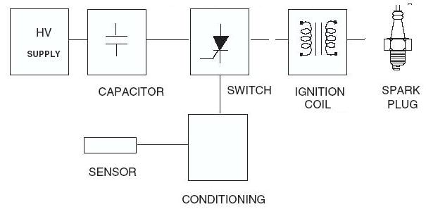
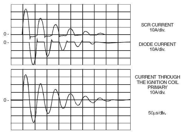
In a CDI system, a charging circuit charges a high voltage capacitor, and during the ignition point the system stops charging the capacitor, allowing the capacitor to discharge its output to the ignition coil before reaching the spark plug.

A typical CDI module consists of a small transformer, a charging circuit, a triggering circuit and a main capacitor. First, the system voltage is raised up to 400-600 V by a transformer inside the CDI module. Then, the electric current flows to the charging circuit and charges the capacitor. The rectifier inside the charging circuit prevents capacitor discharge before the ignition point. When the triggering circuit receives triggering signals, the triggering circuit stops the operation of the charging circuit, allowing the capacitor to discharge its output rapidly to the low inductance ignition coil, which increase the 400-600 V capacitor discharge to up to 40 kV at the secondary winding at the spark plug. When there's no triggering signal, the charging circuit is re-connected to charge back the capacitor.

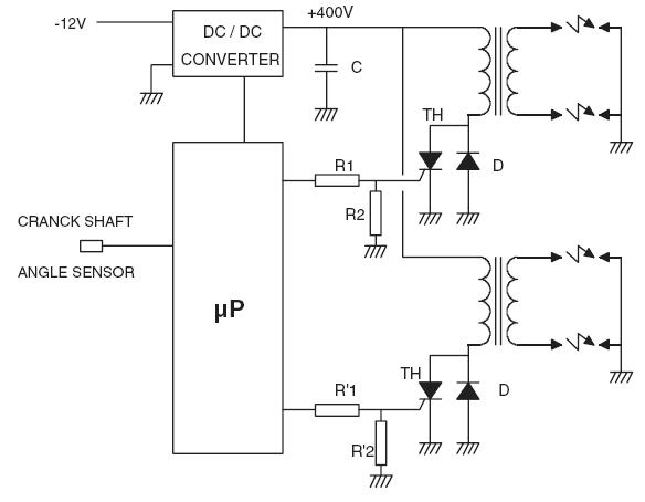
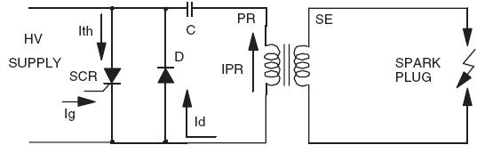
The circuit shuld be similar to the B-type:


threfore without additional information, I have to assume that inside the Yamaha R6 ECU four capacitors are available and charged at about 400V and ready to share their energy with the spark-coils (E = 0.5 x L x I2 = 0.5 x C x V2) when the fire should happen.

Tourque Control
One idea to control the tourque seems to be the disabling of one cilinder firing, seems that GripOne is implementing such strategy.

Looking around I found this connection for the Inductive Transistorized injection (so, not working on my R6):


Some useful links:
McLaren CDI
GripOne Manual

Saturday, March 14, 2009

Putting it together (Con't...)

After one day on the race-track, I've try to understand the YAMAHA R6 (2003 model) ECU signals, these are the garage photos: after I have connected the new weels speed sensors: and the rear one: as is visible in the photo, the inductive sensor does not detect the metal braking disk (LED is OFF), when moving the weel it comes near by the metal the contact is activated (LED in ON): I also take some oscillograms of the engine PRM and rear RPM (output of the inductive sensor), here the 1st gear at RPM=1000:

this is WEELING: